Disclaimer: I'm not an electrician and I would not use this proof-of-concept in reallife because it might be a fire hazard. If you're a electrician and give me some pointers on how good/bad this design is I'd be very thankful
I didn't make a Raspberry Pi project for some time so I thought it was time to start one again. This time I wanted to find a way to control power of any device I plug into a power socket.
All in all it was about 3 hours of work and I'm quite happy with it.
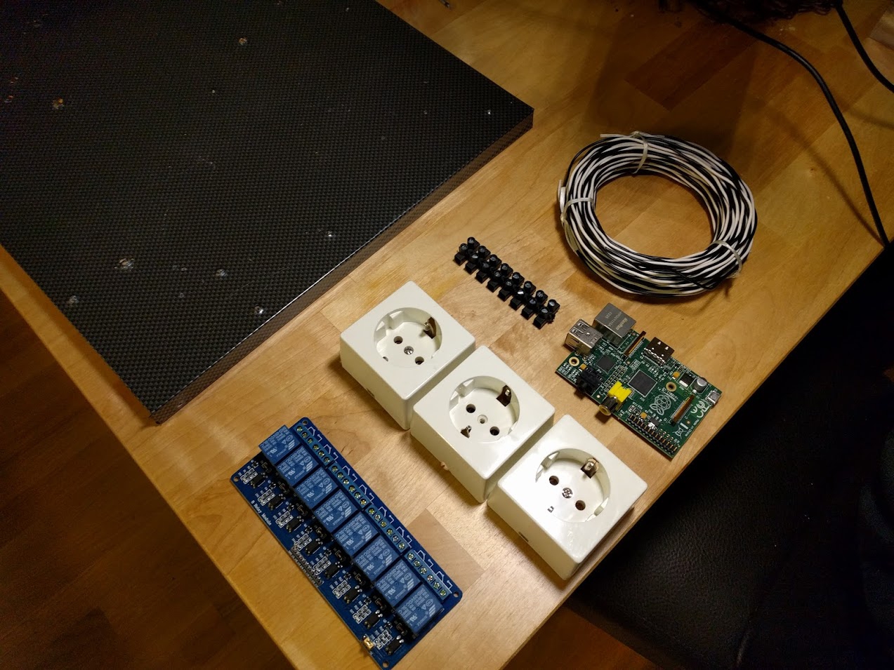
Stuff we'll need
- Raspberry Pi
- A few copper wires that are suitable for high current
- An Relay (I use a 8 relay module I got from ebay for about 10 bucks)
- Power sockets (every hardware store has those)
- Screw terminals
- Something to mout it to (I used a wooden backplate from a previous project. it's full of holes but this is just a proof-of-concept so it'll be fine)
Building it in 5 steps
Step 1: Planning the layout
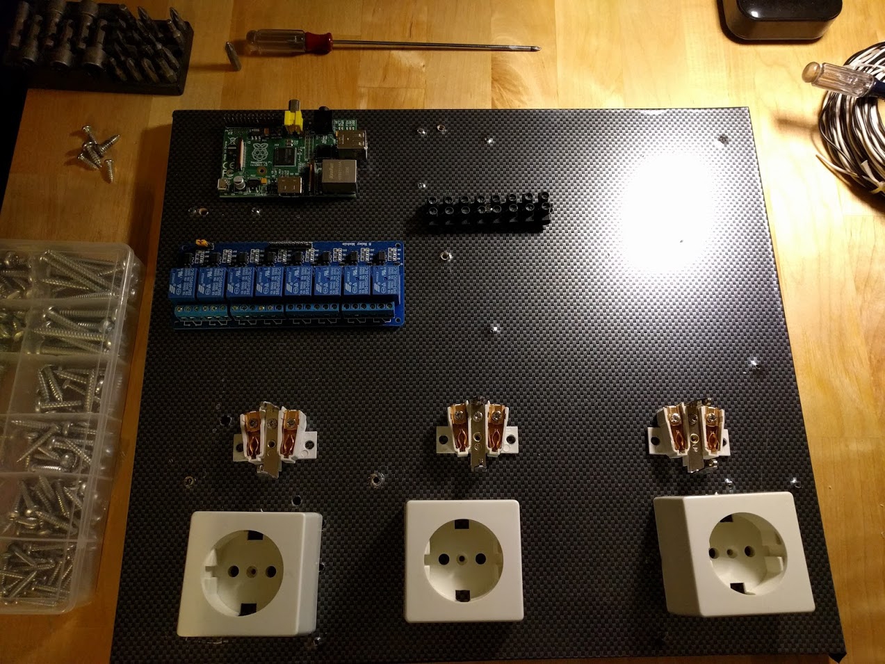
Step 2: Ignore layout from step 1 and mount the stuff where you want
Also take a look at the screw terminal. I dedicated 3 terminals each for neutral and ground. These will go directly to the sockets.
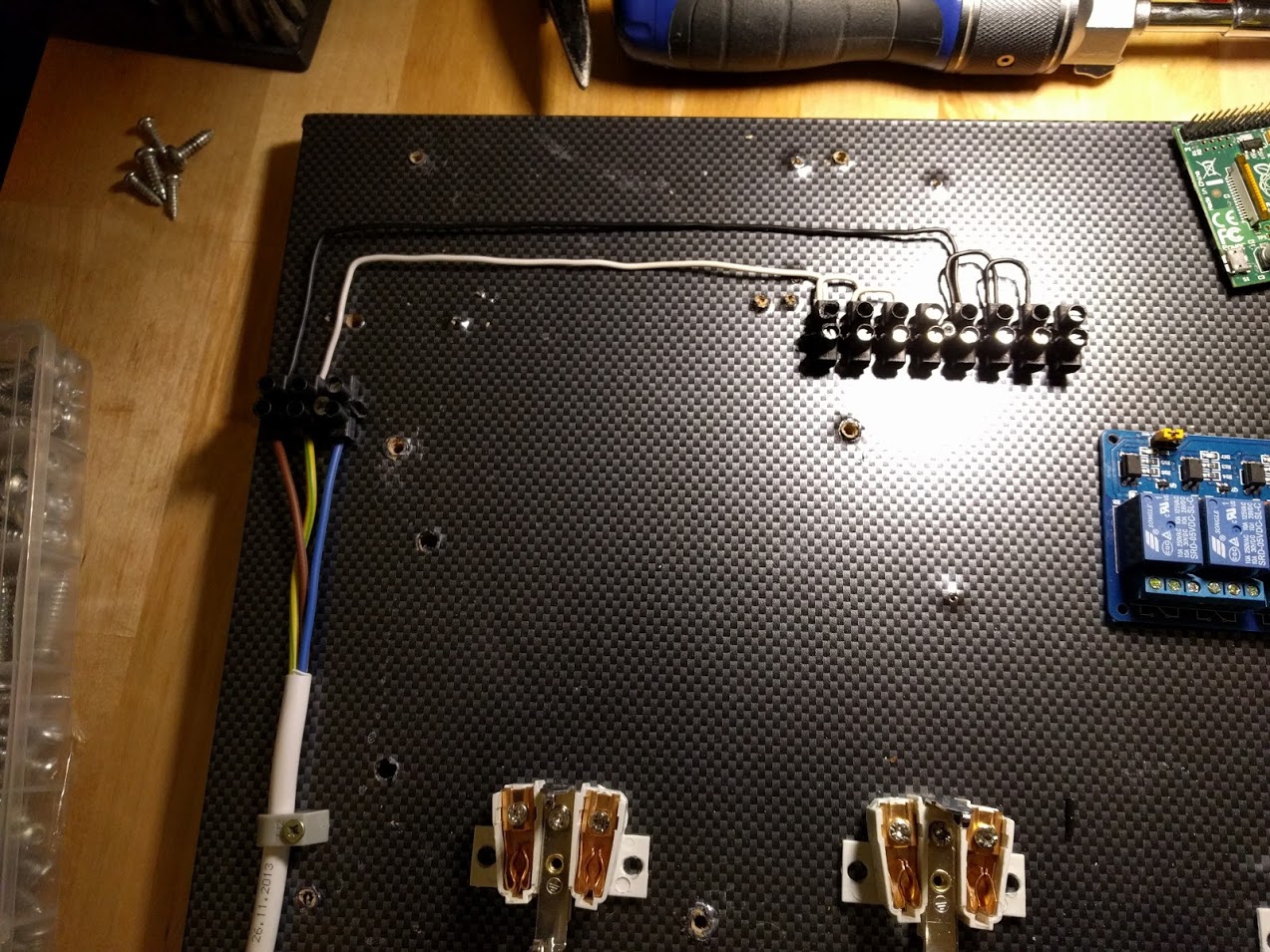
Step 3: Connecting neutral and ground to the sockets
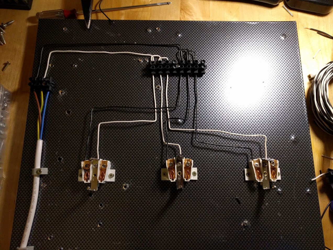
Step 4: Connecting the phase to the relays and those to the sockets
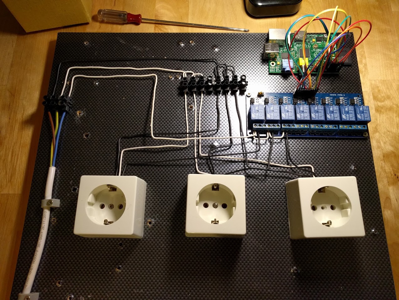
Step 5: Connecting the relay module to the RasPi
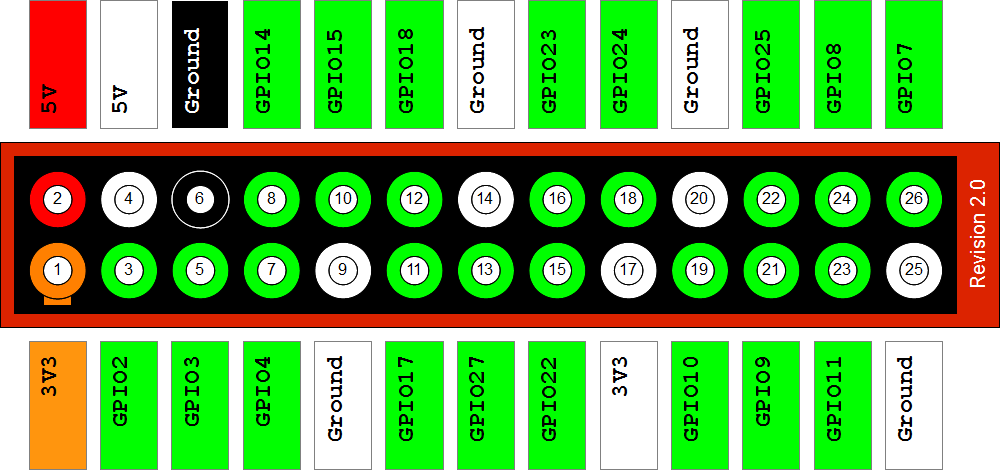
Connect them as follows:
- 5v (raspi) to 5v (relay module)
- Ground to ground
- RasPi pin 16 (GPIO 23) to in 6 (relay board)
- RasPi pin 18 (GPIO 24) to in 7 (relay board)
- RasPi pin 22 (GPIO 25) to in 8 (relay board)
Let's make the software to control it!
btw: I'm using the latest raspbian for this project and am logged in as
root
I'm using the tool gpio which is included in the wiringpi debian package because this way I'm not relying on a library of some programming language. I'm going to do this project in PHP but you can adapt it easily to python or something else.
We'll need some things first
Installing the tool we'll be using to control the pins
We'll install the package wiringpi so we can use the "gpio" command.
apt-get install wiringpiGPIO module for the kernel
Then let's add the gpio module to the /etc/modules file so we can use the GPIO pins. Then let's load it so we don't need a reboot
echo 'w1-gpio' >> /etc/modules
modprobe w1-gpio
Initialization script for the pins
When the raspberry boots all GPIO pins are in some state that we can't use so we'll write a simple initialization script that configures our GPIO pins so we can use them for the relays. Do this for all pins you're using if they are different from the ones I'm using
nano gpio-init.sh
gpio-init.sh
#!/bin/bash
/usr/bin/gpio mode 23 out
/usr/bin/gpio mode 24 out
/usr/bin/gpio mode 25 out

/usr/bin/gpio export 23 out
/usr/bin/gpio export 24 out
/usr/bin/gpio export 25 out
Great now make it executable and testing it:
chmod +x gpio-init.sh
./gpio-init.sh
If you have connected the relay board you'll hear some clicking of the relays. This means it worked.
Now add it to the crontab so it initializes all pins on every reboot
crontab -e
add this line:
@reboot /root/gpio-init.shControlling the pins via webrequests
We want to be able to control the pins from the web so we'll need a webserver and PHP
apt-get -y install nginx php5-fpm
At this point you should be able to connect to your raspberry via a webbrowser.
Configure the server so you can run the gpio command
in /etc/php5/fpm/php.ini
add safe_mode = Off right after the first line (after the [PHP] part) and restart php-fpm with this command: /etc/init.d/php5-fpm restart
Run the visudo command as root and add the following line in the end of the file:
www-data ALL=NOPASSWD: /usr/bin/gpioAlmost done!
Creating the controller script
nano /var/www/html/controller.php
Add these lines:
<?php

$port = $_REQUEST['port'];
$status = $_REQUEST['status'];

//if we got some crazy data, lets not do anything
if(!is_numeric($port) || !is_numeric($status) || $port<0 || ($status>1 && $status<0))
  return false;

//execute the command
@shell_exec("sudo /usr/bin/gpio -g write $port $status");
Finished!
Now you can control the power sockets via HTTP request like this: http://ip.of.your.raspi/controller.php?port=23&status=0
You can now create some program or script that can run from any device on your network that can control the power sockets!
This is how it looks in action:

Comment using SSH! Info